
Leave Your Message

How to Choose the Right Cell Rubber Fender?

Choosing the right Cell Rubber Fender requires more than comparing product sizes or prices. This marine protection device must match the vessel, berth structure, contact energy, and operating environment. A fender that looks suitable in a catalogue may perform poorly when tides, currents, or angled berthing change the impact conditions. Practical selection begins with accurate site information. Record vessel displacement, berthing speed, hull shape, water level, and available installation space. Small details matter.

Engineering teams should review the fender’s rated energy absorption, reaction force, compression limits, and material quality. Reliable manufacturers provide test data, dimensional drawings, inspection guidance, and traceable production records. These documents help confirm whether the Cell Rubber Fender can protect both the vessel and quay without transferring excessive force to the structure. Temperature, seawater exposure, ultraviolet radiation, and repeated compression also deserve attention. Rubber is durable, but it is not indestructible.

A careful assessment includes the mounting system. Bolts, chains, frontal frames, and steel panels must work together under real loading conditions. Installation errors can reduce performance, even when the selected fender is technically correct. That point is often underestimated. Regular inspections should check cracking, tearing, abnormal deformation, loose hardware, and uneven wear. No calculation is perfect. Unexpected vessel movement or structural changes may reveal assumptions that need revision. Consulting qualified marine engineers and following recognized technical guidance creates a safer, more dependable choice. The best decision balances tested performance, site evidence, maintenance access, and long-term operating costs.
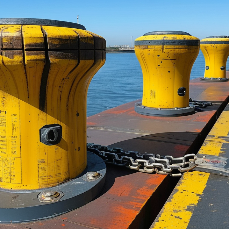
How to Choose the Right Cell Rubber Fender?

Understanding the Working Principles of Cell Rubber Fenders

How to Choose the Right Cell Rubber Fender?

Understanding the Working Principles of Cell Rubber Fenders

A cell rubber fender is a hollow, molded rubber cylinder. It works through controlled axial compression. When a vessel presses against its face, the cylinder shortens and expands outward. This movement converts impact energy into rubber deformation. The attached front frame spreads contact pressure across a wider area.

Its reaction force rises as compression increases. Energy absorption depends on fender diameter, height, rubber hardness, and compression level. It also depends on temperature and loading speed. A fender should not operate beyond its recommended deflection. Excessive compression can increase stress and shorten service life. Small details matter.

During selection, engineers compare berthing energy with the fender’s certified performance data. They also check vessel draft, approach angle, tidal movement, and quay strength. Uneven loading may cause twisting or concentrated wear. In field inspections, loose bolts, cracked rubber, and abnormal bulging deserve immediate attention. I have seen projects focus on energy ratings while overlooking clearance behind the fender. That mistake can restrict movement and damage the mounting structure. Real conditions are rarely perfect. A practical design includes inspection access, replacement space, and allowance for aging. Temperature changes, ultraviolet exposure, and repeated compression slowly alter rubber behavior. Testing records and installation drawings should be reviewed before approval.
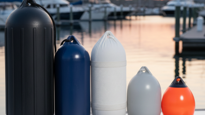
How to Choose the Right Cell Rubber Fender?

Understanding the working principles of cell rubber fenders starts with their nonlinear compression response. As deflection increases, reaction force and absorbed energy rise rapidly. The chart uses normalized engineering relationships based on a representative compression model, with the rated 50% deflection point set to 100%.

A suitable cell rubber fender should be selected by comparing the required berthing energy, allowable reaction force, vessel displacement, installation space, and design deflection. Actual performance must be verified against the manufacturer’s certified test curve and the applicable marine fender standard.

Identifying Vessel, Berth, and Environmental Requirements

Choosing a cell rubber fender starts with the vessel, not the catalog. UNCTAD’s Review of Maritime Transport 2023 reports that over 80% of global merchandise trade moves by sea. This traffic includes feeder ships, bulk carriers, tankers, and fast service vessels. Record displacement, deadweight, hull curvature, and berthing frequency. PIANC Report WG33, Guidelines for the Design of Fenders Systems, considers vessel mass, approach velocity, eccentricity, and hydrodynamic added mass. Do not size from deadweight alone. A smaller vessel may arrive faster.

Inspect the berth carefully. Measure quay height, face structure, panel dimensions, tidal range, and nearby obstructions. Fender reaction must suit the panel pressure and supporting structure. Check vessel contact zones, line loads, crane clearances, and maintenance access. BS 6349-4:2014+A1:2019 emphasizes site-specific design conditions for maritime structures. A fender can absorb sufficient energy yet create excessive reaction force. That is a costly mismatch. Field records are often incomplete.

Environmental conditions can change the selection. Evaluate wind, current, waves, water depth, temperature, salinity, ultraviolet exposure, and floating debris. Tidal movement may increase sliding and shear on the fender face. High temperatures can alter rubber stiffness, while cold conditions may reduce flexibility. PIANC guidance supports checking berthing energy across realistic operating cases, rather than one average scenario. Perfect data rarely exists. State every assumption, test uncertain inputs, and review the design after several months of port operations.

Comparing Fender Size, Energy Absorption, and Reaction Force

How to Choose the Right Cell Rubber Fender?

Comparing Fender Size, Energy Absorption, and Reaction Force

Cell rubber fenders protect vessels and quay structures during berthing. Their selection requires more than matching the vessel’s weight. Fender size affects both energy capacity and contact pressure. A larger fender usually absorbs more energy, but it also needs stronger supports and greater installation space. Field measurements often reveal limited clearance near ladders, bollards, or deck edges.

Energy absorption should match the vessel’s calculated berthing energy, including approach speed, displacement, water conditions, and berthing angle. Engineers should review certified performance data, not rely only on nominal dimensions. Small changes in speed can greatly increase impact energy. That detail is easy to underestimate. I have seen preliminary selections fail because designers used average speed instead of the worst credible approach speed.

Reaction force deserves equal attention. A fender may absorb sufficient energy but still transmit excessive force to the quay wall or hull. Compare the reaction force at the actual design compression, not at an unrelated test point. Check the structure, anchor bolts, contact area, and allowable hull pressure together. A softer fender can reduce reaction force, yet it may require more deflection and maintenance space. The first calculation is rarely perfect. Recheck it with local operating records, manufacturer test data, and an independent engineering review before installation.

Checking Materials, Installation Methods, and Maintenance Needs

How to Choose the Right Cell Rubber Fender?

Material selection should match the working environment, not only the vessel size. Natural rubber offers strong elasticity and useful energy absorption. Synthetic rubber can perform better near oil, chemicals, ozone, or intense sunlight. Check the rubber hardness, temperature range, compression rating, and resistance data. Seawater exposure also matters. During inspections, I have seen suitable fenders fail because their rubber compound was chosen without considering heat and oil contamination. That mistake is easy to repeat.

Installation controls real performance. The fender must sit squarely against a strong, level mounting surface. Use correctly sized bolts, washers, chains, and backing plates. Tighten fasteners evenly, following the engineer’s torque requirements. Misalignment can create uneven compression, visible after only a few berthing cycles. Leave enough clearance for movement, especially where tides or vessel angles change. A load calculation should confirm the fender’s deflection and reaction force before drilling begins.

Maintenance should be practical and recorded. Inspect the rubber for deep cuts, hardening, bulges, permanent flattening, and separation from metal parts. Check bolts for loosening and corrosion. Remove trapped stones or debris from behind the fender. Measure serious deformation instead of judging it by eye. Monthly checks may suit busy berths, while quieter locations may need longer intervals. Still, that assumption should be reviewed after storms, unusual impacts, or changes in vessel traffic. Small cracks matter. They often grow unnoticed.

How to Choose the Right Cell Rubber Fender? - Checking Materials, Installation Methods, and Maintenance Needs

Selection Area Data Dimension Typical Options or Values Practical Selection Guidance Inspection or Maintenance Need
Material and Performance Primary rubber compound Natural rubber, synthetic rubber blends, or rubber compounds modified for oil, ozone, or temperature resistance Natural rubber is widely used because of its high elasticity and energy absorption. Select a specialized compound when the fender will face oils, chemicals, extreme temperatures, or high ozone exposure. Check for hardening, softening, cracking, swelling, surface glazing, and loss of resilience.
Typical rubber hardness Approximately 60–70 Shore A for many marine fender applications Lower hardness generally provides greater flexibility, while higher hardness can provide greater reaction force and resistance to deformation. Confirm the required value through the design calculation. Compare measured hardness with the approved product specification. Significant changes may indicate aging or chemical damage.
Compression behavior Elastic compression with a reaction force that increases as deflection increases Choose a size and grade that can absorb the required berthing energy without exceeding the allowable reaction force on the berth structure or vessel hull. Look for permanent deformation, uneven compression, or areas that do not recover after unloading.
Operating environment Salt water, fresh water, sunlight, temperature changes, abrasion, oils, and marine growth Use marine-grade rubber with suitable resistance to ultraviolet radiation, ozone, water, and abrasion. Chemical exposure may require a dedicated compound. Remove marine growth when it affects movement or compression, and record any chemical staining or abnormal swelling.
Fender dimensions Outside diameter, inside diameter, length, wall thickness, and allowable deflection Dimensions should be selected from berthing energy, vessel approach speed, berthing angle, tidal range, water level, and available mounting space. Verify that the installed dimensions remain within the design tolerance and that the fender is not being compressed beyond its rated deflection.
Installation Method Basic mounting arrangement Cell fender fixed between a supporting structure and a frontal frame or contact panel The frontal frame distributes contact pressure and helps keep the vessel load aligned with the fender system. Inspect the frame for bending, corrosion, cracks, damaged pads, and signs of uneven contact.
Connection hardware Anchor bolts, holding-down bolts, nuts, washers, chains, and connecting plates Use corrosion-resistant or appropriately protected hardware. Bolt diameter, embedment, spacing, and tightening requirements must follow the engineering design. Check for loose nuts, bolt corrosion, elongated holes, damaged threads, and missing washers. Retighten only according to the approved procedure.
Vertical installation Fender axis installed vertically along the berth face Common for quay walls and dolphins where vessel contact is expected over a vertical operating zone. Confirm that the fender remains plumb and that loads are distributed evenly from top to bottom.
Horizontal installation Fender axis installed horizontally or in a designed angled arrangement Used when the berth geometry, vessel contact pattern, or tidal movement requires a different contact orientation. Check for lateral movement, sliding, twisting, and contact outside the intended compression area.
Installation clearance Clearance from adjacent structures, piles, brackets, ladders, and access equipment Provide enough space for the designed compression, inspection, drainage, and replacement work. Avoid sharp edges that can cut the rubber. Keep the clearance free of debris and confirm that no nearby structure restricts the fender’s movement.
Maintenance Requirements Routine visual inspection Recommended at least every 6–12 months, with more frequent checks in heavy-traffic or high-impact locations Adjust the inspection frequency based on vessel traffic, environmental exposure, berth importance, and previous damage history. Record cracks, cuts, abrasion, deformation, detachment, corrosion, and abnormal contact marks.
Post-impact inspection Inspection after abnormal berthing, excessive compression, collision, fire, or major storm events Do not rely only on a visual check when the impact was severe. Review the fender, frontal frame, anchors, and supporting structure together. Measure permanent deformation and verify bolt condition before returning the berth to normal operation.
Acceptable surface condition Minor surface scuffing may be acceptable; deep cuts, exposed reinforcement, major tearing, or severe distortion are not Replacement decisions should be based on the manufacturer’s technical data, design performance, and engineering assessment. Replace or repair components when damage can reduce energy absorption, increase reaction force, or create a detachment risk.
Cleaning and corrosion control Fresh water cleaning, removal of debris, and periodic protection of exposed steelwork Avoid solvents or cleaning chemicals that are incompatible with the rubber compound. Use approved corrosion-control methods for steel components. Check drainage openings, contact surfaces, steel brackets, bolts, and areas hidden by marine growth.
Service-life assessment Condition-based evaluation rather than a fixed replacement date Service life depends on rubber quality, compression cycles, impacts, ultraviolet exposure, temperature, chemicals, and maintenance history. Maintain inspection records with photographs, measurements, impact history, and replacement recommendations.
Final Selection Check Energy and reaction-force verification Calculated berthing energy, design deflection, reaction force, and friction requirements Select the cell fender using a project-specific engineering calculation rather than diameter alone. Review performance if vessel size, berthing speed, berth layout, or operating conditions change.
Structural compatibility Load capacity of the quay wall, dolphin, piles, frontal frame, anchors, and foundation The complete fender system must safely transfer the design loads to the supporting structure. Inspect welds, concrete around anchors, steel deformation, and settlement or movement of the supporting structure.
Replacement planning Availability of lifting access, spare hardware, installation equipment, and safe work space Choose an arrangement that allows damaged fenders to be removed and replaced without unnecessary berth downtime. Keep updated drawings, component records, inspection reports, and replacement procedures on site.
Note: The values and intervals shown are typical engineering guidance. Final selection, allowable deflection, reaction force, compound specification, fastening details, and inspection frequency should be confirmed by the project design calculations and applicable marine-fender standards.

Selecting the Best Cell Rubber Fender for the Project Budget

Selecting the Best Cell Rubber Fender for the Project Budget

Budget-led fender selection should begin with berthing energy, not unit price. PIANC’s Guidelines for the Design of Fenders Systems identify vessel mass, berthing velocity, contact angle, and abnormal impact as core design inputs. A small increase in approach speed can sharply increase absorbed energy. That detail is easy to miss.

UNCTAD’s Review of Maritime Transport 2024 reported 2.4% growth in global seaborne trade during 2023. Busier terminals may face more frequent impacts and faster rubber wear. For a cell rubber fender, compare energy absorption, reaction force, compression limits, and expected service life. Check the complete cost, including frontal frames, chains, bolts, installation, inspection, and replacement access. A low quotation can become expensive when anchorage hardware is excluded.

Site experience also matters. Measure tide range, berth geometry, vessel displacement, and the actual contact pattern. Confirm the rubber compound suits local temperature, saltwater exposure, and ultraviolet conditions. Ask for independent test results, dimensional tolerances, and a clear performance curve. ISO 9001 certification supports process control, but it does not prove the fender meets your design energy. That distinction matters. I have seen projects over-specify reaction force while underestimating maintenance access. The initial design looked safe, yet the operating budget suffered. Recheck the assumptions with the operator, especially when traffic forecasts remain uncertain.