Leave Your Message

How to Choose the Right Cell Rubber Fender?

Choosing the right Cell Rubber Fender begins with understanding the berth, vessel, and operating conditions together. A fender that performs well at a sheltered cargo terminal may fail at an exposed container port. Tides, approach speed, vessel size, berthing angle, current, and temperature all influence the final selection.

Marine engineering author John W. Gaythwaite has emphasized a practical principle: “Fender systems must absorb energy without imposing excessive reaction forces on the berth.” This idea remains highly relevant. A suitable Cell Rubber Fender should absorb the vessel’s kinetic energy while protecting the hull, quay wall, anchor bolts, and supporting structure. The key figures include energy absorption, reaction force, deflection, and allowable compression. Small calculation errors can become expensive damage.

Material quality also deserves close attention. Check the rubber compound, steel flange design, vulcanization process, and test certificates. Ask whether performance data comes from independent testing or only a sales brochure. Real projects often reveal gaps. A fender may meet catalog values but perform differently after years of ultraviolet exposure, saltwater contact, or repeated compression.

Installation details matter just as much. Incorrect bolt spacing, uneven contact, or insufficient backing plates can reduce service life. Maintenance teams should inspect cracks, permanent deformation, loose fasteners, and abnormal wear at regular intervals. There is no universal “best” Cell Rubber Fender. The right choice depends on verified calculations, dependable manufacturing, and honest site information. Sometimes, the best decision requires revisiting an earlier assumption. That is not weakness. It is sound engineering.

How to Choose the Right Cell Rubber Fender?

Understanding Cell Rubber Fender Structure and Purpose

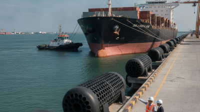
A cell rubber fender is more than a black rubber cushion. Its hollow cylindrical body compresses between a vessel and the quay, while steel flanges, chains, and a front panel control movement. The internal rubber structure stores berthing energy and releases it gradually. This reduces concentrated pressure on the hull and concrete edge. The fender’s purpose is clear: absorb impact, limit reaction force, and protect both surfaces during repeated berthing.

Selection should begin with berthing energy, not product size. PIANC MarCom WG33 recommends considering vessel mass, approach velocity, eccentricity, added hydrodynamic mass, and environmental conditions. These factors can change the required energy capacity considerably. A larger vessel arriving at a modest angle may create a sharper load than expected. Check rated deflection, reaction force, shear resistance, and allowable hull pressure. The mounting system matters too. Poorly aligned chains can twist the fender and shorten its service life.

Port traffic gives this choice real weight. UNCTAD’s Review of Maritime Transport 2024 reports that over 80% of global merchandise trade by volume moves by sea. Every contact point deserves careful engineering. Field inspections should look for cracks, permanent deformation, loose bolts, and uneven compression. It is easy to trust a calculation too much. Real berthing is messier than a spreadsheet. Temperature, aging, installation errors, and unplanned contact angles can reduce performance. A practical specification should include testing, inspection access, and a replacement plan, not only an impressive energy figure.

How to Choose the Right Cell Rubber Fender?

Cell rubber fenders are hollow cylindrical marine fenders designed to absorb berthing energy while limiting the reaction force transmitted to the quay or vessel. The chart shows a normalized performance profile at different compression levels. At the rated compression of 50%, the reaction force and energy absorption are treated as 100%; actual values vary according to fender size, rubber grade, temperature, speed, and manufacturer test data.

Assessing Berthing Conditions and Required Fender Performance

Choosing the right cell rubber fender starts with the berth, not the catalogue. Assess the vessel’s displacement, hull shape, draft, and landing point. Record the normal berthing speed, approach angle, tide, current, wind, and wave conditions. Do not rely on calm-day observations. Small details matter.

Convert these conditions into design energy and required reaction force. A fender must absorb impact energy without exceeding the hull pressure limit. Check compression, deflection, shear movement, and panel contact area. The supporting structure also needs review. A strong fender cannot compensate for weak concrete or poorly designed anchors. That is often missed.

Repeated impacts deserve attention. Temperature, aging, saltwater exposure, and uneven compression can change rubber performance. Select a tested performance curve, then verify it against the project’s design criteria. An independent marine engineer should review the calculations and installation drawings. Field inspections often reveal gaps between drawings and actual conditions. The first estimate is rarely perfect.

It is tempting to choose a larger fender for comfort, but excessive reaction force may damage the vessel or berth. Leave room for adjustment, inspection, and replacement access. Keep records of berthing events, visible wear, bolt condition, and unusual deformation. These observations can improve the next assessment.

Comparing Fender Size, Energy Capacity, and Reaction Force

How to Choose the Right Cell Rubber Fender?

Cell rubber fender selection should begin with the vessel’s berthing energy, not the available space. Fender size determines contact area, deflection range, and installation clearance. A larger unit may absorb more energy, but it can also create excessive reaction force. Measure the quay face, anchor locations, vessel draft, and expected berthing angle before comparing models. Small details matter.

Energy capacity should exceed the calculated berthing energy with a practical safety margin. Include vessel displacement, approach speed, tidal movement, and eccentric contact. Do not rely on a single catalogue figure. Energy performance changes with compression. A force-deflection curve gives a clearer picture than a headline rating. Real projects often reveal an uncomfortable issue: estimated approach speeds may be too optimistic.

Reaction force transfers load into the hull, brackets, and quay structure. Excessive force can damage a lightly framed vessel, even when energy absorption looks adequate. Compare reaction force at the actual working deflection, not only at the maximum value. Check shear movement, sliding friction, temperature, and rubber ageing. Installation tolerances also affect performance. Poor alignment can concentrate pressure on one edge. Request independent test data, dimensional tolerances, and material information. Then review them against the structural calculations and operating conditions. That extra review may feel slow. It is usually cheaper than correcting a misaligned fender after installation.

Selecting Suitable Materials, Accessories, and Installation Methods

Choosing a cell rubber fender starts with the berth, not the catalogue. UNCTAD’s Review of Maritime Transport 2023 states that over 80% of global merchandise trade by volume moves by sea. That traffic creates repeated impact, sliding, salt exposure, and temperature changes. PIANC WG 33 identifies berthing energy, reaction force, friction, vessel approach speed, and hull geometry as core design inputs. These values should guide the rubber compound and fender size.

Natural rubber usually offers strong elasticity and fatigue resistance. Synthetic compounds may perform better against oil, ozone, or extreme temperatures. Check hardness, energy absorption, reaction force, and compression data from independent tests.

Do not compare energy ratings without checking test conditions. The number can mislead. A common field mistake.

Accessories also affect performance. Use a correctly sized frontal panel, low-friction sliding pads, chains, brackets, and corrosion-resistant bolts. UHMW-PE facing can reduce hull friction, but poor fastening can create uneven loading. Installation surfaces must be flat and properly aligned. Survey the quay face before drilling. Confirm bolt torque, chain tension, panel clearance, and drainage paths during inspection.

PIANC guidance supports checking design tolerances and real operating conditions, yet site teams sometimes rely too heavily on drawings. That is risky. A small alignment error can concentrate force at one corner. I would also allow practical space for inspection and replacement, because maintenance access is often underestimated. Record the installed dimensions, rubber batch information, test certificates, and first-contact observations for future adjustments.

Verifying Safety Standards, Maintenance Needs, and Service Life

Choosing the right cell rubber fender starts with evidence, not appearance. Request material specifications, compliance documents, and independent test results. Use the project specification and applicable marine standards as your baseline. Check rated energy absorption, reaction force, dimensions, and allowable compression. These values must match vessel displacement, berthing speed, and berth geometry. A glossy surface proves little. Records matter.

During installation, inspect the body for cuts, bulges, exposed reinforcement, and uneven contact. Use calibrated tools, and record measurements during commissioning. Chains, shackles, bolts, and end fittings also require suitable safety ratings. A fender can be sound while its restraint system is weak. Inspect before heavy seasonal traffic, after severe contact, and at planned intervals. Keep photographs beside dated readings. Small defects grow.

Service life depends on ultraviolet exposure, ozone, abrasion, temperature, storage, and loading cycles. Follow the supplier’s inspection guidance, then adjust it for harsher site conditions. Clean salt and oil deposits with approved methods. Avoid solvents that can attack rubber. Pressure loss deserves investigation, not a quick refill. No inspection plan is perfect. Field teams sometimes underestimate aging because damage develops beneath covers or mounting plates. Review records after every incident, and replace the fender when damage, aging, or test results reduce its safety margin. Leave room for judgment.

How to Choose the Right Cell Rubber Fender? — Verifying Safety Standards, Maintenance Needs, and Service Life

Selection Factor What to Verify Before Purchase Typical Engineering Reference or Acceptance Indicator Effect on Safety and Service Life Recommended Action
Applicable design guideline Confirm that the fender system has been designed and tested in accordance with a recognized marine-fender guideline, including berth geometry, vessel approach conditions, and reaction-force limits. Use the latest project-approved requirements based on the PIANC Guidelines for the Design of Fenders in Ports or an equivalent authority-approved design basis. Establishes a consistent method for calculating absorbed energy, reaction force, deflection, and structural loads. Mandatory
Obtain the design calculation and approval basis.
Required energy absorption Check the berthing energy for the largest and smallest design vessels, including vessel mass, approach velocity, eccentricity, water-level conditions, and abnormal berthing cases. The selected fender arrangement should provide the specified design energy with the required safety factor and without exceeding the allowable deflection. Undersized fenders may bottom out or overload the quay and vessel; oversized fenders may create excessive reaction force. Mandatory
Compare supplier performance curves with project calculations.
Reaction force and hull pressure Verify the maximum reaction force at the design deflection and confirm that hull pressure is compatible with the vessel's side shell, belt, or contact area. Use certified performance data at the specified temperature, deflection, and installation orientation. Do not rely only on nominal fender size. Controls local hull stress, quay-wall loads, anchor loads, and the risk of structural damage during berthing. Mandatory
Require a complete force-deflection curve.
Rubber compound and hardness Review the rubber compound, hardness tolerance, tensile properties, elongation, ageing resistance, and resistance to ozone, ultraviolet exposure, salt water, and oil contamination. The compound should comply with the project specification and relevant rubber-testing requirements. Hardness should be within the specified tolerance; a commonly specified marine-fender hardness is around 60 Shore A, but the design value must be confirmed. Incorrect hardness can change energy absorption and reaction force. Poor ageing resistance can cause cracking, hardening, or loss of elasticity. Mandatory
Request material certificates and test reports for each production batch.
Fender size and installation geometry Check fender outside diameter, height, bore, flange dimensions, panel arrangement, chain layout, clearance, and contact angle against approved drawings. The fender must remain stable throughout its working deflection and must not interfere with ladders, bollards, pile guides, vessel fittings, or maintenance access. Incorrect geometry can cause uneven loading, edge cutting, excessive wear, or accidental disengagement from the quay. Mandatory
Approve shop drawings before fabrication.
Quality control and testing Confirm traceability from raw material to finished fender, dimensional inspection, visual inspection, hardness testing, and performance testing where required by the contract. Test methods and acceptance criteria should be stated in the purchase specification. Each fender should have a permanent identification mark linked to its inspection records. Traceability helps identify production variation and supports warranty, inspection, and replacement decisions. Mandatory
Require an inspection and test plan before production.
Environmental exposure Assess seawater, tidal cycling, temperature range, sunlight, ozone, ice, abrasion, marine growth, chemicals, and possible contact with hydrocarbons. Select a compound and protection system suitable for the actual site environment. Rubber performance data should cover the lowest and highest design temperatures where relevant. Severe exposure accelerates surface cracking, abrasion, swelling, and loss of mechanical properties. Recommended
Include site-specific environmental conditions in the specification.
Fasteners, chains, sliding parts, and panels Check anchor bolts, washers, chains, shackles, sliding pads, frontal frames, steel panels, coatings, welds, and corrosion allowances. Metallic components should be designed for the calculated reaction and shear loads and protected with a suitable corrosion-control system for the exposure category. Ancillary hardware often fails before the rubber body, allowing the fender to shift, rotate, or detach. Mandatory
Inspect the complete system, not only the rubber element.
Routine inspection frequency Establish inspection intervals based on vessel traffic, berthing severity, tidal movement, exposure, and the consequences of failure. Perform visual checks routinely and conduct a documented detailed inspection at least annually; high-risk berths may require more frequent inspections. Early detection of cuts, cracks, excessive compression, abrasion, loose hardware, and abnormal deformation reduces unplanned outages. Routine
Record condition photographs, measurements, and corrective actions.
Common damage limits Inspect for deep cuts, exposed reinforcement, tearing, permanent deformation, severe abrasion, bulging, debonding, and damage around the mounting area. Replace or obtain an engineering assessment when damage affects the load path, mounting security, designed contact area, or the fender's ability to achieve its specified performance. Surface marks may be cosmetic, but structural cuts and mounting damage can cause sudden loss of protection. Safety Check
Do not define acceptance only by appearance.
Maintenance requirements Review cleaning procedures, corrosion control, chain adjustment, bolt-tightening requirements, panel alignment, and access for inspection or replacement. Maintenance should follow the approved operation and maintenance manual. Avoid solvents, paints, or repair materials that are incompatible with the rubber compound. Correct maintenance limits corrosion and mechanical damage without degrading the rubber surface. Recommended
Keep spare hardware and repair records available.
Expected service life Ask for a service-life assessment based on berthing frequency, design energy, environmental exposure, inspection history, and the condition of the entire fender system. A planning expectation of approximately 15–20 years is often used for well-designed and well-maintained marine rubber fender systems, but actual life can be shorter or longer. Service life is governed by fatigue, abrasion, ozone and UV exposure, over-compression, chemicals, temperature, and hardware condition—not age alone. Plan Ahead
Base replacement on condition and performance, not calendar age alone.
Replacement decision Compare current measured condition with the original design requirements and determine whether energy absorption, reaction force, geometry, and attachment security remain acceptable. Replacement is normally justified when the fender cannot reliably meet the approved performance requirements or when damage compromises safe attachment. Prevents both premature replacement and continued operation with an unreliable protective system. Decision Point
Use a documented engineering assessment for borderline cases.
Engineering note: The values and intervals shown are practical reference points rather than universal acceptance limits. Final selection should be based on the approved berth design, vessel data, local environmental conditions, applicable regulations, and project-specific manufacturer test documentation.