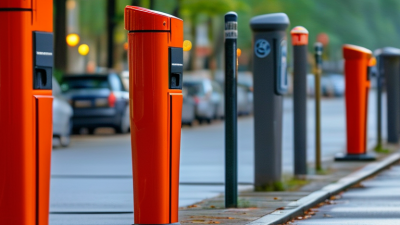
Why Choose Locking Bollards for Global Security Needs?
Security decisions often begin with a simple question: what must be protected, and from which risks? Locking Bollards provide a practical answer for sites that need controlled vehicle access without creating a permanent visual barrier. They can protect entrances, loading areas, private car parks, retail forecourts, and public-facing facilities. A locked post can remain upright during restricted hours. It can also be lowered when authorised vehicles need passage.
“Effective security should support normal operations, not obstruct them,” says David Allinson, a recognised access-control specialist with experience in physical perimeter protection. This principle explains the value of Locking Bollards. They combine visible deterrence with straightforward daily control. Keyed, padlocked, removable, and automatic models serve different operational needs. The right choice depends on traffic frequency, impact expectations, maintenance capacity, and local site conditions.
Practical details matter. A busy delivery entrance may need a robust automatic system. A small private driveway may only require a manual locking post. Stainless steel can suit coastal environments, though regular inspection remains necessary. Corrosion still happens. Poor installation can weaken even a high-quality product. That is easy to overlook.
Global security needs are not identical. Climate, vehicle types, staffing, and access routines vary widely. Therefore, product selection should follow a documented risk assessment, not a fashionable specification. This article examines how Locking Bollards support layered protection, operational flexibility, and responsible site planning. They are not a complete security strategy. Used carefully, they can become a dependable part of one.
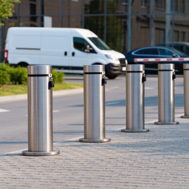
Why Choose Locking Bollards for Global Security Needs?
Locking bollards combine controlled access with practical vehicle mitigation. They remain secured until an authorised user unlocks them. Models may use keys, padlocks, or electronic release systems. This protects service lanes, loading bays, pedestrian areas, and emergency routes.
The need is substantial. The World Health Organization’s Global Status Report on Road Safety 2023 records about 1.19 million annual road deaths worldwide. Not every incident involves deliberate intrusion, but vehicle movement still creates serious risk. A correctly specified bollard can stop unauthorised cars, slow careless drivers, and preserve a clear boundary. PAS 68 and IWA 14-1 testing help compare impact performance. However, test results depend on vehicle mass, speed, foundation design, and installation quality. A strong post in weak concrete is not strong protection. This detail is often overlooked.
Tips: Match the bollard to the threat, not only the appearance. Confirm impact ratings, locking hardware, drainage, lighting, and maintenance access. Leave enough turning space for emergency vehicles. Keep a manual release plan nearby. Keys can disappear. Electronics can fail. Regular inspections should check corrosion, hinge movement, lock alignment, and ground damage. Security teams should also review traffic patterns after installation. A barrier that blocks deliveries may encourage unsafe workarounds. That is an uncomfortable design failure, but it is still a design failure.

Locking bollards combine controlled vehicle access with physical perimeter protection. The chart shows the nominal impact-test speed benchmarks represented by ASTM F2656 M30, M40, and M50 classifications: 30, 40, and 50 miles per hour respectively. These benchmarks describe vehicle-impact testing levels and should not be treated as a performance guarantee for every locking bollard. Actual protection depends on the bollard design, foundation, installation, operating method, and site-specific risk assessment.
Locking bollards can help control vehicle access while supporting a stronger perimeter security plan. Their value depends on more than appearance or locking hardware. The foundation, spacing, installation depth, and operating routine all affect real-world performance.
ASTM F2656 ratings provide a practical reference for impact resistance. In this range, K4 addresses a 15,000-pound vehicle traveling at 30 mph. K8 represents the same vehicle at 40 mph. K12 represents 50 mph. These tests examine how the barrier performs during a controlled vehicle impact, including vehicle penetration beyond the barrier line.
That distinction matters.
A rating is not a guarantee for every site. Pavement conditions, soil strength, drainage, and nearby structures can change the result. Experienced security planners review traffic patterns, emergency access, and the required stopping distance before selecting a bollard system. Locking mechanisms also need regular inspection, especially where dust, rain, or repeated daily use are common.
One detail is easy to overlook. A high impact rating cannot correct poor installation. Engineering review and documented maintenance are essential. In practice, the best solution may combine rated bollards with gates, lighting, cameras, and clear driver guidance. The strongest plan is often less dramatic, but more carefully matched to the site.
Locking bollards control vehicle access while keeping pedestrian areas visibly protected. The right locking method depends on traffic volume, staffing, climate, and emergency planning. Manual bollards use a key, handle, or removable lock. They suit smaller sites with predictable access schedules. Their design is simple, but operation can become slow during rain, darkness, or shift changes.
Automatic bollards respond to a control system, remote signal, or access reader. They work well at busy entrances, where vehicles arrive throughout the day. Sensors, warning lights, and clear sightlines are essential. A fast mechanism is not automatically a safe one. Poor installation can create hazards for drivers, cyclists, or maintenance teams. Regular inspections should check movement, drainage, locking parts, and visible damage.
Fail-safe security modes require careful explanation. Some systems lower or release during power loss, supporting emergency access. Others remain raised, protecting the perimeter but restricting entry. The safer choice depends on evacuation routes, fire planning, and the site’s operating risks. No mode is perfect. In field assessments, I have seen teams choose automatic control without planning manual override access. That small omission caused delays during maintenance. A reliable specification should document power behavior, authorized access, reset procedures, and inspection intervals. Local accessibility and safety requirements also deserve review before installation.
Locking bollards can control vehicle access while preserving pedestrian movement and emergency routes. Their value depends on tested impact performance, not appearance alone. IWA 14-1 and PAS 68 provide structured ways to assess this protection. Both standards examine how a barrier responds when struck by a defined vehicle at a defined speed and angle. The test record may include vehicle mass, impact direction, penetration distance, and barrier condition after impact. These details matter beside a gate, outside a loading area, or across a busy entrance.
IWA 14-1 is an international classification framework for vehicle security barriers.
PAS 68 is a widely used impact test specification developed for similar security applications. Their ratings should not be treated as interchangeable without checking the original test report. A bollard tested with a small vehicle may not suit a heavier delivery truck. Installation also changes performance. Weak foundations can undermine strong steel. Real sites are messier than test yards.
Tips: Ask for the complete test classification, not only a headline rating. Confirm the tested vehicle mass, speed, angle, and penetration result. Inspect the proposed foundation design and drainage conditions. Check whether the locking mechanism remains practical during rain, dust, or frequent daily use. A site survey with an experienced security engineer can reveal risks that a catalogue misses. Some decisions still need review. That is normal.
Why Choose Locking Bollards for Global Security Needs?
Locking bollards can control vehicle access while preserving a clear pedestrian route. Their value depends on tested performance, safe operation, and correct installation. ISO 22343 focuses on vehicle security barriers, including impact testing and performance ratings. It helps security planners compare resistance levels against realistic vehicle threats. However, a bollard’s rating does not automatically validate the complete site design. Road width, foundation depth, vehicle approach speed, and spacing all matter.
UL 294 addresses access control units and systems, especially electrical operation, interfaces, and controlled entry. A locking bollard connected to keypads, readers, or emergency release equipment should be assessed as part of that access system. EN 12453 applies to powered doors, gates, and barriers. It emphasizes safe movement, force limitation, protective devices, and emergency controls. Sensors should detect a person or vehicle before the bollard creates a dangerous movement.
Details matter.
In field planning, teams should review test reports, wiring diagrams, maintenance access, and local approval requirements. A bollard may pass an impact test yet fail operational checks because drainage is poor or sensors are misaligned. That assumption needs challenging. Compliance is not a label placed on one product; it is evidence linked to a defined configuration and use case. Independent inspection, documented commissioning, and scheduled testing improve reliability. Still, standards can be interpreted differently across jurisdictions, and project teams should confirm the current editions with qualified local professionals.
| Standard or Regulation | Primary Scope | Relevant Compliance Requirements | Application to Locking Bollards | Typical Verification Evidence |
|---|---|---|---|---|
|
ISO 22343-1:2023 Security and resilience — Vehicle security barriers |
Vehicle security barrier performance, vehicle impact testing, and performance classification. | The barrier is assessed through a defined vehicle impact test method. The test considers the vehicle type, vehicle mass, impact speed, impact direction, barrier configuration, and vehicle penetration or stopping performance. | A locking bollard may be suitable for hostile vehicle mitigation when its complete installed configuration has been tested or engineered for the required threat level. The assessment should include the bollard, foundation, anchorage, locking mechanism, control cabinet, and surrounding pavement. | Independent impact-test report, declared test configuration, installation drawings, foundation details, performance classification, and documented maintenance requirements. |
|
ISO 22343-2:2023 Security and resilience — Vehicle security barriers |
Application and selection of vehicle security barriers for protective security planning. | Barrier selection should reflect the site threat assessment, vehicle access routes, operating conditions, required security function, installation environment, and the consequences of vehicle intrusion. | Locking bollards can support layered protection by controlling authorized vehicle movement while creating a physical obstruction against unauthorized entry. The security design should also address pedestrian routes, emergency access, visibility, lighting, and operational procedures. | Site risk assessment, vehicle access strategy, security layout, operating procedure, emergency override plan, and compatibility review with other perimeter-security measures. |
|
UL 294 Standard for Access Control System Units |
Safety and performance of access-control system units, including control equipment and associated access-control functions. | Applicable equipment is evaluated against requirements for construction, electrical safety, access-control operation, endurance, attack resistance, and other criteria specified by the certification program and product configuration. | UL 294 is not an impact-rating standard for bollard posts. It may be relevant to the access-control components used to operate a locking bollard, such as the controller, credential reader, communication equipment, power supply, and release logic, when those components fall within the evaluated system scope. | Certification documentation for the specific control equipment, wiring diagrams, access-control architecture, power-supply information, credential-management records, and configuration instructions. |
|
EN 12453:2017+A1:2021 Safety in use of power operated doors, gates and barriers |
Safety requirements and test methods for power-operated doors, gates, and barriers used by people. | The powered installation should be designed to reduce risks from crushing, shearing, impact, trapping, and unintended movement. Safety functions may include protective devices, control systems, stopping or reversing behavior, warning measures, and appropriate operating modes. | A powered locking bollard installation should be assessed as a complete machine or barrier system where applicable. The design should consider vehicle and pedestrian interaction, movement zones, visibility, obstruction detection, emergency release, control positioning, and safe behavior after power loss. | Risk assessment, technical file, safety-function verification, force or protective-device test results where applicable, operating instructions, maintenance schedule, and declaration of conformity documentation. |
| Electrical and Control-System Design | Reliable operation of the locking, detection, communication, and emergency-release functions. | The design should define normal state, secure state, power-loss behavior, fire-alarm interface, emergency override, access authorization, fault indication, and protection against unauthorized control. | Locking bollards can provide controlled physical access without relying solely on electronic authorization. However, the final system must clearly specify whether the bollard remains raised or lowers during power loss, fire alarm, controller failure, or emergency operation. | Cause-and-effect matrix, single-line diagram, control-panel specifications, battery or backup-power calculations, emergency-release test records, and cybersecurity or network-segmentation documentation where applicable. |
| Installation and Lifecycle Management | Long-term performance, inspection, maintenance, and safe operation of the installed barrier. | The installation must preserve the tested or engineered performance of the barrier. Drainage, corrosion protection, foundation strength, anchorage, traffic loading, impact damage, and periodic functional testing should be addressed. | Locking bollards are most effective when the structural installation, locking mechanism, controls, warning signs, road surface, drainage, and service access are designed as one system rather than as separate components. | As-built drawings, installation records, commissioning checklist, inspection log, preventive-maintenance plan, replacement-part specifications, and records of corrective actions after impact or malfunction. |